Canadian Siborg Systems Enhances LCR-Reader Bluetooth Data Logger to Include Component Testing Using BOM and Visual PCB Layout
WATERLOO, ON, June 10, 2024 /PRNewswire/ -- The new version of the LCR-Reader Bluetooth Logger now allows users to load a circuit board list of components (BOM), PCB layout file, and the PCB image. After a simple adjustment/scaling of the image, the program allows users to select a component for testing by clicking either on its location on the PCB image or in the linked component list.
The new Bluetooth feature uses a low-energy Bluetooth connection to a PC with a received dongle and dedicated app. When connected, the LCR-Reader will send all measurement data, including the main and secondary measurement values and test parameters, to the receiving software. The results can then be exported to a spreadsheet. The ability to automatically record values in real time is exceptionally useful for quality control and situations where recording values is crucial.
The LCR-Reader with Bluetooth allows users to remotely record measurement data in real-time, control test settings from the computer, and perform pass/fail sorting. Additionally, the LCR-Reader Bluetooth model allows users to create test profiles that are stored on the computer and can be activated while testing components, simplifying incoming tests of components. Using preset test conditions is very critical for some components, such as small inductances and capacitances, for which the highest test frequency is preferable. Moreover, preset test parameters minimize operator errors while testing. The software is also capable of sorting components with a preset tolerance, making Pass/Fail results easily recognizable on the computer screen.
The new LCR-Reader Data Logger main interface window, shown in the attached figure, illustrates the vast amount of information available when testing a component: test signal, test frequency, impedance, dissipation factor, quality factor, test current, tangent, voltage drop on the component, component type, and value.
Test mode can be easily changed from the computer screen: LCR/ESR/Diode mode (RLCD), DC/LED mode (RD), and Voltage measurement mode (V, LCR-Reader MPA only). Once the component is connected, the test result is readily available on the computer screen with Pass/Fail status shown and recorded in the database after the "Start" button is clicked.
Additionally, the program allows users to use the Analog Signature Tool to analyze the nonlinear I-V response of a component on the PCB and compare it to the reference I-V response image stored in the database, simplifying the diagnosis of the assembled PCB. When the Analog Signature is used on the assembled PCB, the result obtained applies to the whole PCB, including all connected components. If the Analog Signature differs from the reference obtained for a "proven to be good" assembly, it indicates a problem with either the component itself or other components or connections on the circuit board. By analyzing possible scenarios of failure, a set of signatures can be created representing typical failures for the tested board, allowing quick diagnosis of circuit board failures.
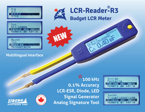
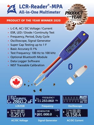
The new software version supports three latest models of the LCR-Reader product line: the award-winning LCR-Reader MPA, the high-frequency LCR-Reader R2, and the latest multilingual model LCR-Reader R3. It should be noted that the LCR-Reader MPA does not have the Analog Signature Tool but still allows component testing and saving the test results in a spreadsheet format.
A comparison of the technical specifications of various LCR-meter models available from Siborg Systems is shown in the Model Comparison Sheet.
All LCR-Reader and Smart Tweezers models, including the new multilingual LCR-Reader R3, are now available at Siborg's online store, DigiKey, and Amazon, as well as from our distributors in India and China.
Contact:
Michael Obrecht
5198889906
[email protected]
SOURCE Siborg Systems Inc



Share this article